I
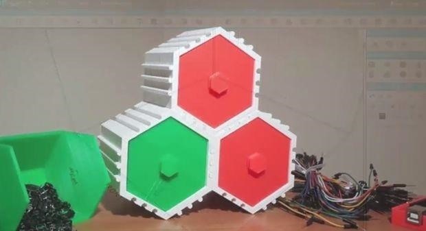
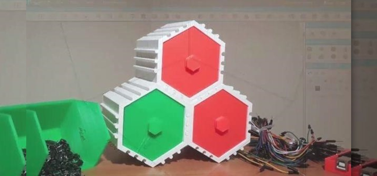
In this step by step process, we are going to create the above Stackable Hexagon model using the Browser-based 3D modeling and sculpting software called SelfCAD.
SelfCAD has a one-month free trial and thereafter you will be paying $4.99/m or $39.99/yr.
Step 1: Overview of What We Are Creating


Required Models to Make up the Hexagonal Model

The first image above gives us an overview of how the Stackable hexagon looks like in the 3D view.
The model has several useful parts shown above which when combined they create the Stackable Hexagon.
To model and print any 3D object, you have to first model separate parts and then assemble them.
To model our Hexagon Draw, we need to analyze the Parts of it. In our first model above we can note that we have seven parts, that is;
Container that contains the draw inside it,
Hexagon Shaped Net- found at the end of the container. It is used to prevent the drawer from sliding out or falling from the container.
Stackable Bars- To make the drawer stackable.
Drawer Box- This is the box that is used to store and carry the items that you need to put inside it.
Drawer Pulling Hand- You can use it to drag the items from the box.
Tag Place- Used to put tags to the stuff inside the drawer.
Front Part- It prevents the drawer from going completely inside the container.
So those are the main elements that make up the hexagon.
Step 2: Creating the Container


To model the container, we need to model the hexagon too with Void inside it, and we can create it by first creating the Hexagon solid box and then subtract another smaller one inside of it so that we can get the final result which is the container body.
To start, we need first to use the Shape Generator (found in the Create Section).
Set the No. of Edges to 6. Decrease the Bottom and Top Radius to 40 in order to get the correct straight box shape.
Adjust the Height as you want, in our case we used 90 then click Finalize.
There is also another way to create the Hexagon box, that is, by going to the Basic Shapes Section (Found on the left side) and choose Cylinder. Set the Vertical segment to 6.
Step 3: Creating a Smaller Hexagon Box

To design it, we need first to duplicate our model. Duplicating a model in SelfCAD can be done in three ways. The first way is by creating another shape using the Shape generator tool with the same parameters.
After creating the new model that is exactly the same as the one before you can see their difference by selecting one of them (By clicking on the object or by selecting it on the object list) and press M to move it (or select the Move tool found in the transformations section).
Delete the new object by selecting it and press delete on your Keyboard.
The second way to duplicate the object in SelfCAD is by copying the object. You can do this by selecting the object and in the Edit Menu Select Copy offsets then click copy.
We need now to subtract one box from the other. But before we do that we need to scale one of them to be smaller than the other one and create the void inside the box to become two which we can use to put the drawer inside.
Step 4: Subtracting One Box from the Other


After creating the solid hexagon box Now we need to subtract one box from the other but before we do that, we have to scale one of them to be smaller than the other one to shape and create the void space inside the box to become a tube that we can use to put drawer inside it.
To scale one of them select only one of them and choose the Scale Tool from transformations section in the toolbar or press L in your keyboard.
To have a better vision and see the two objects clearly while scaling, make the appearance of them in wireframe mode selecting wireframe option on the left hand-side as shown in the first image above.
Now let's scale. Drag from the center scale point to scale in the 3 dimensions and to scale the object overall
And then drag the upper point to scale in Y dimension or to scale vertically.
And now let's use mesh and wireframe together. Select the bigger box and move it up.
The idea of doing this is to make the subtract object go completely inside the big box
so that we can subtract the complete void area to form and create the container tube.
Rename the smaller box to "Subtract" and then select both of the objects and choose Boolean tool from tools section in the toolbar. Choose difference and select the subtract object.
And check keep the original object and press apply
Now we have the tube container part of the drawer
Select the big box and delete it.
Hide the smaller box because we will need it to create the drawer and let's continue making the container tube as we have seen in the example picture.
After creating drawer container tube, Here we come to the next step in our Basic modeling process.
We still need two parts in the container to finish it. The hexagon shaped net at the end of the container tube to prevent the drawer from sliding out or falling from the container and the bars and void lines attached to the container to make it stackable, (they are shown in the 4th image above.)
Step 5: Creating the Hexagon Shaped Net


To create the main part of the net we can do that in many different ways let me show you the easiest one of them.
First, we need to make a copy of the container tube from the edit menu. Choose copy offsets and set all parameters to zero And click on copy. Close copy offsets tooland get scale tool and start to scale the copy in the 3 dimensions, as shown in the second image above.
Now scale it vertically And move it to the vertically to the ground Now we need to complete the net So unhide the hidden solid box and move it away for now.
To make the other parts create a box from basic shapes toolbar To be able to create the box while you see the other objects in the scene.
Uncheck hide all objects option and make all parameters to have a value of one (As shown in the 4-th image above).
Now we need to increase one of its dimensions. Select the container and the main part of the net and rotate them till they are aligned with the box you have created.
Now move the box between them and start to scale it to fit this space Make a copy of it using copy offsets tool and move it to the other side.
Select both of them and choose to group them from the edit menu. Now we need to rotate them around the center of the group.
Step 6: Rotating the Object Around the Centre of the Group


After grouping the boxes we have created, we need now to copy them in a rotation to form and complete the hexagon net.
The idea of grouping the two boxes is to make the gizmo point in the center of them So we can rotate both of them from the center point easily using copy offsets.
Let's do it.
I have created a single box to show you how I can rotate it around the center point.
Let's hide the tube to have a better vision.If I select this box and get rotation tool.You can change the position of gizmo point by saved location according to the shape from these lists.It will be rotating around its self, as shown in the first image above.
But in this case, we need to rotate the box around the center point of the hexagon shape. So we will manually move the gizmo point (By selecting Manual Gizmo Position of the box to this center point. And then start to rotate it around Y dimension of this gizmo (as shown in the second image above).
However, we need to input a specific rotation angle which is the 360 degrees divided by 6 angles to be 60 degrees for every angle.
But we need to make a copy and then rotate it and then another copy and then rotate it again.
So let me show you a much easier way to do so using copy offsets.
We need to rotate so we will choose Rotation.
Now let's type our angle which is 60 degrees around Y dimension. And then to type the copies we need only 2 copies because every box here needs only 2 copies to complete its side. So I will type here 2.
Before I click on copy, I will get rotation tool to make sure that the gizmo position is in the center point as we want after that click on copy (Check the settings in 3rd image above).
Here we get the final net shape we want (As shown in the 4th image above), select the boxes plus the main part of the net and group them.
Here we have our net. you can then select it and give it the same color of the tube or any color you want.
Step 7: Creating the Bars and Voids


Now we need to create the bars and voids to be able to stack the drawers together.
But before we do this we need to increase the thickness of the tube so that we can create void bars inside it.
To do so, we need to select the outer polygons and scale them.To select polygons, select the shape and choose polygon selection tool from region selection section in the tools toolbar as shown in 1st image above.
We need first to understand how polygon selection tool works. If you Enabled single polygon it will select only 1 polygon depending on segments so it will only select every polygon among segments where you point with your mouse if you turn it off.
Also, It will select polygons depending on Tolerance the more tolerance you put the more polygons it select ignoring the lines of segments, as shown in 4th image above.
Select all outer polygons and get scale tool.
Here we have the Y dimension at the value of 90 we want to keep this because we don't want to scale them vertically.
Drag the center scale point to scale them in the three dimension till you get the suitable thickness And then write back the value of 90 here in the Y dimension After finishing, click anywhere in the viewport to finish scaling.
Get move tool and move the object to the ground again.
Now we need to create the bars and void bars inside the tube body.
Create a cylinder from basic shapes toolbar.
Uncheck "Hide All Objects" option. Type three at the top radius and the same value at bottom-radius. You are free to change it but I think three is the most suitable value for the bars.
Comparing to the size of the tube I have here. Set the height to 90. And set the segments to 6 segments and then finalize the shape. We need to rotate it to be parallel to the tube.
To have a better vision angel switch to orthographic mode (as shown in the 7th image above)and start to rotate it until It is parallel to the tube. Now we need to move it to the edge of the tube and start to distribute it around it plus we need to make voids inside the tube.
Step 8: Moving the Model to the Edge of the Tube and Distributing It


After creating the bar, Now we need to move it to the edge of the tube and start to distribute it around it
plus we need to make voids inside the tube.
Let's Start.
First, move the bar to the bottom edge of the tube but make it attached to the tube
to have a better control use the values of move tool In Z Dimension (as shown in first image above).
Now we need to make 2 copies one of them on the right side of the Bar and the other one in the left side.. to do so I will use copy offsets and we will need to move it in X-dimension.
The distance between every two lines in selfCAD by default is 50 so to create a near copy I will write 10 and click on copy (as shown in 2nd-image above).
To make another copy on the other side with the same distance I will type 10 but with minus this time to be -10 (As shown in the 3rd image above)
Now we have both copies on each side. And we need to copy them to be on the other 2 sides.
Select the bars and group them, and we need 2 copies of this group, Select the bars and get copy offsets toolset all parameters to zero and make 2 copies.
Select one group of the 3 groups and get rotate tool and move the gizmo to the center point. Now type the angle of rotation which will be 120 degrees around Y dimension. (As shown in 4th image above).
Now select the remaining group and rotate it around the center point with the angle of 240 (As shown in 5th- image above)
Step 9: Making the Voids


Select the tube and the groups and rotate them 60 degrees around the center point Select one group and make a copy of it using copy offsets. And rotate it back to the first position using 60 degrees angle If you are rotating clockwise it will be positive value And if the other direction it will be negative value so to rotate back this group I will use the value of -60 (as shown in second -image above).
Now I need to make the same area of the outside bars carved into the tube inside.
So I will rotate or mirror the group around the outer edge of the tube to get it inside the tube.
To do this, I will get the rotation tool and move gizmo to this point and type 180 degrees around Y dimensions.
Now we need to make two copies of the group and rotate them to the remaining sides. Select the group and make two copies with copy offsets tool. (as shown in 4th image above)
Select one group and get rotate tool move gizmo point to the center point.
The first group with 120 degrees and the second group with 240 degrees.
To make the voids inside the tube we need to use Boolean tool, but before We do this we need to scale the void bars vertically to make sure that it will cut the whole area inside the tube, (as shown in 6th-image above).
Move the tube vertically to be in the middle of bars (as shown in 7th-image above). Now we are ready to make the Boolean.
Select the tube and the 3 void groups. Get Boolean tool and choose difference and select the 3 groups in subtract list and press apply (as shown in the 8th-image above).
Move the tube to the ground again Select the tube and the other bars and group them and give them the same color and show the hidden layers and we are done.
Step 10: Modeling the Drawer


In the previous step, we had finished creating the container tube where we will put the drawer inside and now we need to model the drawer.
But we have the hexagon box so we will show it and use it in modeling the drawer, as shown in the first image above.
To move the box to its original place where we created it the first time, select the box and get move tool.Move it to Zero point. Set all directions to zero.
Now we need to rotate it to be aligned with the tube. (as shown in the second image above). To have a better vision get orthographic mode and top view, start rotating the box around Y Axis.
After finishing rotating get the side view in orthographic mode (You can do this by selecting Camera then left) and Move the box vertically to the ground but here we have the net at the bottom of the tube.So we need to move it a little up. In Y Axis.
To have a better vision make the tube wireframe, (you do this by selecting Wireframe in the left hand-side).
To be accurate use the parameter of Y-axis in move tool.
Now we need to scale the box to be the same void area. Get scale tool and use parameters.
Get the mesh appearance back to the tube.
Now we are ready to start modeling the drawer.
And we will do so by making another copy and subtract it from the box to give us the space where we can use to put items inside.
Select the box and isolate it (as shown in the 5th-image above).
Make a copy of it using copy offsets tool. Make one of them in wireframe view, select the other one and start to scale it (as shown in the 6th image above).
Select the outer box and hide it.
Then select the inner box and From region selection choose vertex selection.
Select 6 of the vertex and drag them (as shown in the 7th Image above). Unhide the outer box and give it a Mesh view (as shown in 8th Image above).
Select the two boxes and get Boolean tool, choose difference and select the inner box. And press apply
Here we have created the drawer (as shown in the 9th image above)
Step 11: Modeling the Hand of the Drawer


Hide everything and get shape generator from create section in the toolbar.
Set number of edges to 6 edges.
Reduce the height to 19 and add a new segment (as shown in the first image above).
Reduce the top radius to 61 and add a new segment.
Increase the top radius (as shown in second-image above). But I want the top radius to be at the same size of the bottom radius of the previous segment.
So to know the value of it click on the previous segment to show its parameters in the parameters menu and copy it and go to the current segment and paste it in the value of the top radius.Now we have the same radius.
Add a new segment reduce its height to 23 as shown in the 3rd image above.
Add another segment and reduce its height and top radius to 5 and 74 respectively and then finalize the shape.
Show the hidden drawer and start to scale and move the hand of the drawer until it become suitable and rotate it to be aligned with the drawer (as shown in the 4th-image above).
Use orthographic mode to have a better vision (To do this select Camera then top).
Now we are done with 1 drawer let's see how to print and use it in the next step
Step 12: Printing the Drawer


In the last step we finished modeling 1 unit of the drawer and now we need to know how to print it and use it
In the first step we have said that in order to print and use any object you have first to model its printable parts and print every part and then assemble them to start using the object.
So to start printing our drawer we need first to determine the objects that need to be printed in separated way.
In our case we have the tube and the box inside and the hand of the drawer.
We can group the hand of the drawer with the box inside and group the hexagon net with the tube.
Now we can start printing the tube and then the box inside it.
A good thing about selfCAD is that it lets you print the selected objects only.
If you don't have any objects selected it won't print anything and will tell you to choose an object first to print
So To print the tube, Select it and go to file menu and choose print (as shown in the first image above).
Here selfCAD shows you a list of common 3d printer to choose from, so if your printer listed here you would choose the type of your printer.
If you don't have your printer listed here. Click on custom FDM printer and start to enter details of it here. After that start printing by clicking on "Generate G code"
If you want to change the settings of the printer press on settings icon beside the name of the printer Or you can delete it and create a new printer.
For me I will choose delta Go printer (as shown in the 5th image above). And you can add more printers and in my case, I will add hero printer.
After that, you can toggle between them. Let's say for example that I need to print my model on my printer which is delta go printer.
Actually, SelfCAD doesn't print the model, but it creates the Gcode that printer can use to print your model .. so to generate the Gcode selfCAD uses a Slicer that slices the object you print to many slices or layers which make the gcode readable by your printer because the printer print the model as layers and that forms and creates the final object in real.
You can change the quality of printing;
Extra fine means very high quality printing and that affects number of slices and time that would be spent to print the model by your printer. Also it lets you choose the material of printing and layer height and many more parameters in this list.
To know what every parameter does, hover with your mouse cursor on the question mark. It will show you useful hints about every parameter (as shown in the 6th image above).
To start generating the Gcode. Click on (Generate Gcode).
Here it is currently processing the layers that printer will take in the printing process.
Here you got the result it has sliced the tube into five hundred eighty-nine Layers and it would take 15 hours and 24 mins (as shown in the 7th image above).
The red surrounding area is a skirt an extra area. To prevent the shape falling while printing and you can easily remove it after printing the object by cutting it (as shown in the 8th image above).
We have an icon here to tell us how much time will every process take, we have 2 ways to decrease time of printing (shown in the 9th image above).
The first way is to decrease the quality of printing. Here we have decreased the time of printing by half. To 7 hours and 46 mins.
The other way is to change the parameters of printing process like layer height and printing speed beside the quality of printing. Here we can see that the time has greatly reduced from 15 hours to only 1 hour.
So what I wanted to say that the speed of printing depends on the parameters you put in here in the settings and the quality of printing you want.
When you are done.
Click on save Gcode so that you can download the Gcode file and use it in the 3d printing by your printer.
to print the drawer do the same thing with it.






Be the First to Respond
Share Your Thoughts